
Electro Optical Terahertz Pulse Reflectometry
EOTPR: The world’s fastest and most accurate fault isolation system.
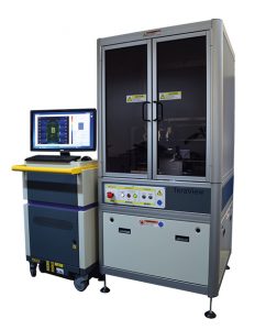
 The EOTPR 3000 system is configured with a manual probe station to meet today’s tough FA environment which requires to isolate fault location in minutes rather than hours or days, while maintaining the EOTPR’s world leading sub-5 μm fault isolation accuracy.
Key Features
- Manual probe station for quick sample runs
- Data acquisition time of less than 5 sec. per pin.
- User friendly software to capture data.
- Uses GGB high frequency probe tips.
- Supports any pitches between 50 μm to 1.1 mm.
- Less than 5 μm distance-to-defect fault isolation accuracy.
Product Features
- Patented technology.
- More than 270 mm signal penetration into DUT.
- Improved SNR over EOTPR 2000.
Technical Specification
| EOTPR pulse rise time | 6 ps (based on processed data) Defined as the time for the reflected impulse from the end of the high frequency probe to rise from 10% to 90% of its maximum value |
| Accuracy | Able to locate a feature on 50 Ω coplanar waveguide positioned close to the high frequency probe with precision of ± 5 µm |
| Range | Up to 270 mm from contact with probe in a typical package |
| Input Impedance | 50 Ω nominal |
| Signal to noise | 94 dB |
| Laser stabilisation | Laser power stabilisation prevents laser power fluctuations during measurement |
| Measurement time | Rapid scan delay line offers measurement times of less than 5 seconds per pin |
| Time-based jitter | < 30 femtoseconds |
The EOTPR 4000 system is configured with an automated probe station which is capable of placing the probe tip to +/- 5 μm precision, while maintaining the EOTPR’s world leading sub-5 μm fault isolation accuracy.
This combination allows users to directly probe TSV tips and copper pillars.
Key Features
- Pre-scan station to map contact location and height.
- Data acquisition time of less than 5 seconds per pin.
- Software that will drive the automated probe station and pre-scan station.
- Availability of both manual mode and automated mode for probing.
- User interface software to manage data display and recipe creation.
- Probe tip placement.
Key Components
- 5 μm accuracy auto-prober.
- Pre-scan station for contact point mapping.
- Automated probe station that can also be operated in manual mode.
- EOTPR probe head.
Core Unit
| THZ source | Laser gated photo-conductive semiconductor emitter |
| THz detector | Laser-gated photo-conductive semiconductor detector |
| Laser | Ultra short pulsed laser |
| A/D converter | 16 bit |
| TDR pulse rise time | 6 ps (based on processed data) Defined as the time for the reflected impulse from the end of the high frequency probe to rise from 10 % to 90 % of its maximum value |
| Accuracy | Able to locate a feature on 50 Ω coplanar waveguide positioned close to the high frequency probe with precision of ± 5 µm |
| Range | Up to 270 mm from contact with probe on a 50 Ω strip line |
| Input impedance | 50 Ω nominal |
| Channel input connector | 1 mm |
| Probe configuration | In addition to fitting within the TeraView supplied station, the probe is suitable for mounting on the Alessi REL-4800 parametric probe station made by Cascade Microtech (not supplied) |
| Dimensions (ex. probe station) | 600 mm (w) x 1320 mm (h) x 1000 (d) mm |
| Weight (ex. probe station) | 220 kg (480 lbs) |
| Electrical power requirements (ex. probe station) | 90 VAC to 250 VAC, 47 to 63 Hz single phase |
| Operating temperature | 18 °C (64 °F) to 30 °C (86 °F) |
| Operating humidity | Up to 80 % (non-condensing) |
Automated Probe Station
| Probe station modes of operation | Auto BGA probing (for BGA > 200 μm), semi-auto probing mode (see specifications below) or manual probing mode |
| Probe tip pitch | 30 μm to 1.2 mm with compatible GGB and Cascade probes |
| Probe tip calibration | Quick probe calibration to determine: • Position of the signal and ground tips • Probe tip pitch |
| Device under test size | 5 mm x 5 mm to 70 mm x 70 mm |
| Device mounting | Devices under test are mounted to the probe station with reusable Gel-Pack mounts |
| Device under test contact type | Compatible with BGA, LGA and microbumps |
| Minimum solder ball diameter | 30 μm (semi-auto mode) |
| Minimum LGA pad size | 30 μm x 30 μm (semi-auto mode) |
| Device under test pre-scan time | Less than 60 seconds (single 16 mm stripe) |
| Measurement time per pin | Less than 5 seconds (no co-averaging) |
| Software | A full software suite to enable data collection and analysis with the automated probe station |
| Data file format | Data files will contain the following information: • Device name/type (user specified). • Pin locations measured. • Measured date. • Task information/comments (user specified). |
| Microscope | Microscope supplied with CCD camera |
| Dimensions (estimated) | 1000 mm (w) x 1900 mm (h) x 900 (d) mm |
| Weight (estimated) | 250 Kg |
| Environment | As per the core unit |
Watch the EOTPR 4000 demonstration above.
 The EOTPR 4500 system couples the EOTPR’s world leading sub-5 µm fault isolation accuracy with the next generation in automated probe stations. The purpose built auto prober has been designed to address the needs of today’s most advanced IC packaging technology, and can probe down to 5 µm pads on IC packages up to 150 mm x 150 mm in size.
Needle-nose probe tip
Key Features
- Purpose built auto prober for advanced IC packages.
- Can probe down to 5 µm pads on IC packages up to 150 mm x 150 mm.
- Availability of guided fully manual, semi-manual and automatic probing modes.
- Data acquisition of less than 5 seconds per pin.
- User interface software to manage recipe creation and data display.
- Sub-5 µm fault isolation accuracy.
- ODB++ file import for contact mapping and recipe generation with optional QuickView software.
Key Components
- IC package high precision auto-prober that supports the substrate size of 150 mm x 150 mm.
- In-built 3D line scan camera system to map contact locations and heights.
- EOTPR core unit.
- Optional DUT (device under test) heater supports up to 260°C.
- Optional DUT chiller supports down to -40°C.
- Optional needle nose probe tip to land on target as small as 5µm.
System Specifications
| Dimensions | 60 (w) x 132 (h) x 100 (d) cm |
| Weight (approximate) | 220 kg (core unit) |
| Electrical Power Requirements | 90 VAC to 250 VAC, 47 to 63 Hz single phase |
| Operating temperature | 18 °C (64 °F) to 30 °C (86 °F) |
EOTPR Capabilities
| TDR pulse rise time | Less than 6 ps (based on processed data) defined as the time for the reflected impulse from the end of the high frequency probe to rise from 10 % to 90 % of its maximum value. |
| Accuracy | Able to locate a feature on 50 Ω coplanar waveguide positioned close to the high frequency probe with precision of ± 5µm. |
| Range | Up to 270 mm from contact with probe on a 50 Ω strip line. |
| Input Impedance | 50 Ω nominal |
| Channel Input Connector | 1 mm |
Automated Probe Station
| Modes of operation | Full auto probing mode, semi auto probing mode, or guided manual probing mode (see specification below). |
| Probe tip pitch | 50 μm to 1.2 mm |
| Probe tip mount | Allows probe position to be adjusted in x, y, and z. Probe tip angle can be adjusted to ensure signal and ground tip co-planarity. |
| Probe tip calibration | Quick probe calibration to determine: •Position of the signal and ground tips. •Probe tip pitch. |
| Device under test size | 5 mm x 5 mm to 150 mm x 150 mm |
| Device mounting | DUTs are mounted to the probe station in a device specific fixture and held in place with vacuum. Reusable Gel-Pack mounts can be used for small samples. |
| Optional device under test heater | Enables a device under test mounted to the chuck to be heated to a maximum temperature of 260 °C |
| Probe tip placement accuracy | +/- 0.5 µm |
| Device under test contact type | Compatible with BGA, LGA and microbumps. |
| Minimum solder ball diameter | 5 μm (manual mode), 30 μm (semi auto mode), 200 μm (full auto mode) |
| Minimum LGA pad size | 5 μm x 5 μm (manual mode) 30 μm (semi auto mode) |
| Device under test pre-scan time | 5 seconds per 9 mm wide stripe •<150 seconds to scan 140 mm x 140 mm DUT •<60 seconds to scan 70 mm x 55 mm DUT •<45 seconds to scan 40 mm x 25 mm DUT |
| Dimensions | 150 (w) x 190 (h) x 150 (d) cm |
| Weight (estimated) | 250 kg |
| Power Requirements | 1 x 110V to 250V, 10A, 50-60 Hz single phase |
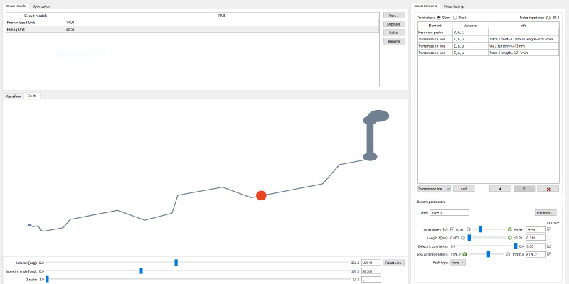
 The EOTPR QuickSim is a simulation tool for EOTPR users which can ease the interpretation of the EOTPR waveforms. This is a software package that can quickly and accurately simulate the EOTPR waveform recorded from a known good device sample measurement.
The software requires only limited DUT (Device Under Test) information to generate an accurate model (e.g. trace length) and does not require the full 3D design file of the DUT.
Once generated and optimised, models can be used to accurately locate faults in a failed device.
Simulation Steps
- Import measured EOTPR waveforms
- Construct circuit model of device (typically < 5 minutes)
- Perform optimisation (typically < 1 minute)
- Extract fault location
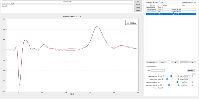
The example above shows the EOTPR QuickSim simulation of a bare substrate.
Good fit is obtained between the measured (black curve) and simulated (red curve) waveforms.
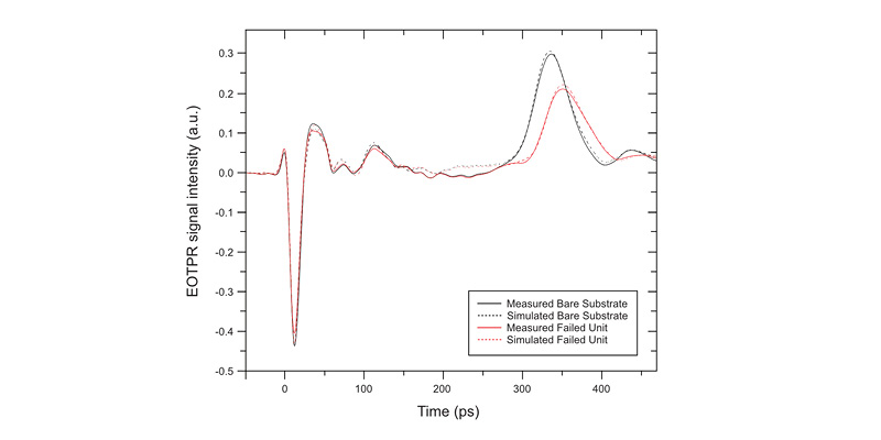
The figure above shows the measured and simulated waveforms for two 2.5D devices. EOTPR QuickSim was the used to generate a circuit model of a bare substrate waveform (solid black curve). The resultant simulated bare substrate waveform is shown by the dashed black curve in the figure. The different features of the measured waveform are reproduced well in the simulated model. The optimized bare substrate model was then used to find the best fit to the measured failed unit waveform (red solid and dashed curves). The model puts the fault 100 µm after the bare substrate termination, in good agreement with the confirmed fault location.
Watch the film below for a demonstration of the software.
The EOTPR QuickView software package enables importing ODB++ files to automatically generate a device model and then visualise the trace and the calculated fault location.
EOTPR QuickView enables visualisation of imported trace structure and displays real fault location.